Project lines onto a surface
Project lines onto a surface consisting of 3dface entities.
Access methods
8 Toolbar:

8 Menu: ComputationalCAD Project lines
7 Command entry: CC:LINES:PROJECT
Dialog
Select faces:
Select the 3dfaces defining the surface
Select lines:
Select the lines to project.
Specify projection direction
[X/Y/Z/Ucs/2Points]:
Select the
projection
direction.
<X>:
The lines are projected in global
X-direction
<Y>:
The lines are projected in global
Y-direction.
<Z>:
The lines are projected in global Z-direction.
(default)
<Ucs>:
The lines are projected in UCS
z-direction.
<2Points>: The lines are projected
in a user defined projection direction. The following dialog occurs:
Specify first point
Select the first point of the projection direction.
Specify second point
Select the second point of the projection direction.
Insert on layer [Current/by Face/by Line]:
Select the layer assignment for the
projected lines.
<Current>: The projected lines
will be inserted on the current layer. The colour of each line will be the
colour of its 3dface.
<by Face>: The projected line
will be inserted on the layer of the 3dface the line was projected onto.
(default)
<by Line>: The projected lines will
be inserted on the layer of the original lines.
Delete original lines
[Yes/No]:
Specify if the original
lines shall be
deleted.
<Yes>:
The original lines will be
erased.
<No>:
The original lines will not be erased. (default)
Summary
The lines will be projected onto faces lying above and below the line in projection direction. For each line, start and end point are projected onto the surface. If a line crosses an edge of a face in projection direction, it will be split at the projected intersection point of edge and line. Consequently, there will be more projected lines than original lines in a general case.
The projection onto a specific face fails if the normal vector of the face is perpendicular to the projection vector or if the line to be projected runs parallel to the projection direction.
If the lines are inserted in the current layer, the colour of each line will be the colour of the face it is projected onto.
Example
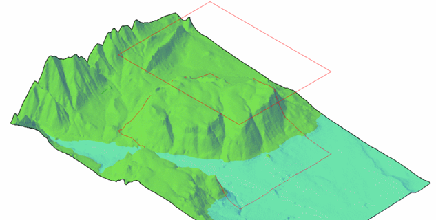
Figure 18: Four lines in the xy plane and their projection onto a surface
Command line prompt:
Number of lines projected : 850
Number of failed faces : 0
Faces parallel to projection direction: 0
Lines parallel to projection direction: 0