Compute contour lines
Compute contour lines of a surface consisting of 3dface entities.
Access methods
8 Toolbar:

8 Menu: ComputationalCAD Compute contour lines
7 Command entry: CC:FACES:CONTOUR
Dialog
Select faces:
Select the 3dfaces defining the surface
Specify reference plane [Wcs/Ucs/3Point]:
Specify the plane to refer the
elevation.
<Wcs>:
The elevation refers to the z-axis of the global coordinate system.
(default)
<Ucs>:
The elevation refers to the z-axis of the UCS coordinate
system.
<3Point>: The elevation
refers to the z-axis of a user defined coordinate system
Specify start elevation:
Enter the start elevation. The elevation refers to the
z-axis of the reference plane specified above. Expects any numeric value.
Default is <0>.
Specify end elevation:
Enter the start elevation. The elevation refers to the
z-axis of the reference plane specified above. Expects any numeric value.
Default is <0>.
Specify spacing:
Specify the spacing between two contour lines. The
spacing refers to the z-axis of the reference plane specified above. Expects a
positive, non-zero value. Default is <1>.
Insert on layer [Current/by Face/by
Elevation/by Index]:
Specify on
which layer the contour lines shall be
inserted.
<Current>: The contour lines will be
inserted on the current layer.
<by Face>: The contour
lines will be inserted on the layer of the respective face.
<by
Elevation>: The
contour lines will be inserted on a layer with the layer name containing the
elevation of the contour line. The layer will
be
created it if it does not exist. (default) Following dialog is
displayed:
<by Index>: The contour lines will be inserted on a
layer with the layer name containing the index of the contour line, starting
from 1.
The layer will be created it if it does not exist. Following dialog is
displayed:
Specify prefix string
Specify the prefix of the layer name if <by Elevation> or <by Index>
has been selected. Default is ‘Contour_line_’.
Summary
The contour lines will be inserted as AutoCAD 3d polyline entities. Regardless of the selected layer insertion method, the color of a segment is always set to the color of the respective face. The contour lines are computed in planes parallel to the specified reference plane.
Example
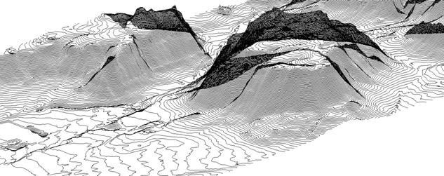
Figure 20: App. 180k contour lines in 2045 polylines computed from app. 107k faces.
Command line prompt:
Failed intersections : 0
Degenerate intersections : 0
Total number of segments : 180439
Total number of polylines: 2045