Slice a surface
Slice a surface consisting of 3dface entities.
Access methods
8 Toolbar:

8 Menu: ComputationalCAD Slice surface
7 Command entry: CC:FACES:SLICE
Dialog
Select faces:
Select the 3dfaces defining the surface.
Specify origin point of plane:
Select the origin point of the
slicing plane.
Specify point on positive x-axis:
Select a point on the positive
x-axis of the slicing plane.
Specify third point on plane:
Select a third point on the slicing
plane.
Specify point on side to keep or [keep Both
sides]:
Select a point on the side
of the slicing plane to keep or ‘B’ to keep both sides. Default is
<B>.
Keep coplanar faces
[Yes/No]:
Select if faces coplanar to
the slicing plane shall be kept. Default is <Yes>.
Summary
The command slices a surface consisting of AutoCAD 3dface entities analogously to the AutoCAD slice solid command. Faces that intersect the slicing plane will be erased and replaced by two or three faces that respect the slicing plane. The orientation of the faces will be maintained.
Example
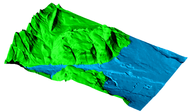
Figure 21: A sliced surface. Faces below slicing plane coloured blue, faces above slicing plane coloured green
Command line prompt:
Failed faces : 0
Faces sliced : 2170
Faces remaining: 109647

Figure 22: Sliced surface – detail (top view)