Project points onto a surface
Project points onto a surface consisting of 3dface entities.
Access methods
8 Toolbar:

8 Menu: ComputationalCAD Project points
7 Command entry: CC:POINTS:PROJECT
Dialog
Select faces:
Select the 3dfaces defining the surface
Select points:
Select the points to project.
Specify projection direction
[X/Y/Z/Ucs/2Points]:
Select the
projection
direction.
<X>:
The points are projected in global
X-direction
<Y>:
The points are projected in global
Y-direction.
<Z>:
The points are projected in global Z-direction.
(default)
<Ucs>:
The points are projected in UCS
z-direction.
<2Points>: The points are
projected in a user defined projection direction. The following dialog
occurs:
Specify first point
Select the first point of the projection direction.
Specify second point
Select the second point of the projection direction.
Insert on layer [Current/by Face/by
Point]:
Select the layer assignment
for the projected points.
<Current>: The
projected points will be inserted on the current layer.
<by
Face>: The projected points will be inserted on the layer
of the 3dface the point was projected onto. (default)
<by
Point>: The projected points will be inserted on the layer
of the original point.
Delete original points
[Yes/No]:
Specify if the original
points shall be
deleted.
<Yes>:
The original points will be
erased.
<No>:
The original points will not be erased. (default)
Point to keep
[Highest/Lowest]:
<Highest>: The point with
the highest z-coordinate is kept.
(default)
<Lowest>: The point with the
lowest z-coordinate is kept.
Example
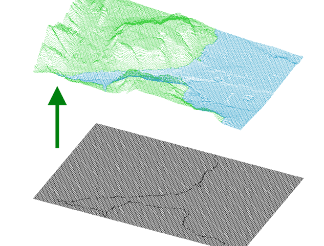
Figure 11: 54k vertices (black) projected onto a surface consisting of 104k faces (not shown for clarity)